You are using an out of date browser. It may not display this or other websites correctly.
You should upgrade or use an alternative browser.
You should upgrade or use an alternative browser.
Jet City Picovalve thread!
- Thread starter GilmourD
- Start date
wagdog
Ack
I finally took mine out of the box and got to play it last night. I hate it and I like it is my verdict. Right out of the box with tone controls at 12 o'clock and manipulating the Preamp and Poweramp, it has that nice overdrive Marshall type tones. The more I play it, it is starting to sound sterile so tube changes will be necessary. The sweet spot on this amp is the preamp around 4-6 with the Poweramp set to about 5-7. This was both for the 2W and the 5W settings. The bright had a very small effect and not really a notable change. As for the 2W/5W switch, I like the volume level on 2W but it sounded to bassy. With the amp set to 5W, much more bright but with those Chinese tubes - edgy and brittle.
First mod when I get the chance will be tubes. I believe that this will give it some life. This amp will be great to record with in the future. As for tube testing on the output tube, I will be trialling a 5881 and maybe an EL34. This amp was designed to be hot so trying to get a clean sound is tough. Stock out of the box I could get a Plexisound, Marshall modern sound and even the wanky nasty tones that many like that I don't. Either way I will enjoy this and will mod as I see fit. I do want to explore sounds of the THD Univalve as there are circuit commonalities and Andy Marshall is the designer for both systems. Mods may be closer to replicate that if I am no thrilled with the quick mods.
The 2w/5w switch is a pentode/triode switch - the triode tone is awful and lifeless, imo. I hardwired the 5w and repurposed the switch.
Tubes are a must, and lowering the grid leak on v2:1 to something sensible - as it is, it's 2m. I've got a webpage going w/my mods (I'm going to update it tonight or tomorrow, it's kind of rough right now): http://wagner-usa.net/picovalvemods/
Going to do this tonight if the wife and kid give me time.Interesting...
Maybe If I get a chance later I'll catalog all the values of components as they are stock. I'd like to get an idea of what's going on before I start making changes.
Sent from my DROID RAZR HD using Tapatalk
Odd... Unless I've gone bonkers (which is entirely possible) they seem to have skipped some numbers in the component lists.
Here's the capacitors.
And here's the resistors.
I left the missing parts listed but blank, just in case I did in fact lose my mind.
Here's the capacitors.
Code:
Part    Value
C1      22p
C2      1000p
C3      22p
C4      22u
C5      22000p
C6      22000p
C7      220p
C8      470p
C9      22000p
C10     22000p
C11     100u
C12     220u
C13     220p
C14
C15
C16
C17     220p
C18     220u
C19
C20     330u
C21
C22
C23     100u
C24
C25
C26
C27
C28     15000u
And here's the resistors.
Code:
Part    Value    Tol.    Wattage
R1      1M       1%
R2      68K      1%
R3      100K     1%
R4      220K     1%
R5      1.5K     1%
R6      220K     1%
R7      10K      1%         2
R8      100K     1%
R9      1.5K     1%
R10     10K      1%         2
R11     820      5%
R12     1M       1%
R13     33K      5%
R14     1M       1%
R15
R16     100K     1%
R17
R18     220K     1%
R19     220K     1%
R20
R21     250      1%
R22     5.6K     1%
R23
R24     1K       5%        5
R25     4.7K     1%
R26     100K     1%
R27     220K     1%
I left the missing parts listed but blank, just in case I did in fact lose my mind.
wagdog
Ack
This is awesome, thanks. I can't get into my amp 'til later, but I'll take a look and confirm this (and the post above).Odd... Unless I've gone bonkers (which is entirely possible) they seem to have skipped some numbers in the component lists.
The major differences that I noticed were that C21 (cap from secondary 16 ohm tap to ground) is entirely not even in there, C5 (cap from V1:2 plate to grid of v2:1) and C6 (cap from master volume pot in series with 4.7K resistor to grid of the power tube) are 10 times the value that they should be, and C2 (cap from V1:1 plate to gain pot) is 1000pF instead of the 2200pF on the schematic.
I imagine these things might make some differences in tone, but I'm still relearning some of the minutiae of tube amp circuitry and can't remember the exact differences these would make.
I imagine these things might make some differences in tone, but I'm still relearning some of the minutiae of tube amp circuitry and can't remember the exact differences these would make.
btownbobby
n00b
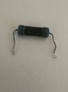
My Jet City Picovalve blew the R21 resistor. From the info provided I see that it is 250 ohms, 1% tolerance. is there a voltage rating? Also, could it be a symptom of something else ?
R21 is the cathode resistor on the power tube, which is 250 ohms and 2W from the factory. I've seen some guys swap that out for a 250ohm 10W resistor because the stock 2W unit is enough but kinda being pushed at the same time.
btownbobby
n00b
Thank you very much. I appreciate your help.


