Jet City Picovalve thread!

GilmourD

Eater of Worlds
Staff member
Since a few of us seem to be getting our hands on these things, I figured I'd start a thread where we could compile all the different things we've done to them and different mods that can be done.

First thing I did to mine was this: http://www.byocelectronics.com/board/viewtopic.php?f=9&t=46224&sid=29e402c646fb1fd8191fcca85eca0ba7

Even with the stock Chinese tubes it took away the fuzzy midrange and overpowering bass and allowed the treble to breath a bit.

This is the next mod I plan on doing: http://www.byocelectronics.com/board/viewtopic.php?f=9&t=46325&sid=29e402c646fb1fd8191fcca85eca0ba7

As far as tubes go, right now I have a JJ ECC83S in V1 and an EH 12ax7 in V2 with an EH 6L6GC. I just got a JJ 6CA7 in the mail that I'm going to try and I'm going to swap in different combos of all those preamp tubes I rediscovered (my other thread).

Oh, and I'm running mine through a Jet City JCA24S 2x12. I still have the back closed. I haven't had a chance to remove the screws on the open back flap.

What do you guys have in mind?
 
Even with the stock Chinese tubes it took away the fuzzy midrange and overpowering bass and allowed the treble to breath a bit.

Sounds like I could run one in stereo with my VJ and cancel out the sonic issues with both amps. :lol:
 
Sounds like I could run one in stereo with my VJ and cancel out the sonic issues with both amps. :lol:
I've been thinking about running my Vox AC4TV8 in stereo with this. However, this really simple, one-resistor mod totally changed the usability of the Picovalve without changing its actual core character.
 
Mine should be here this week.

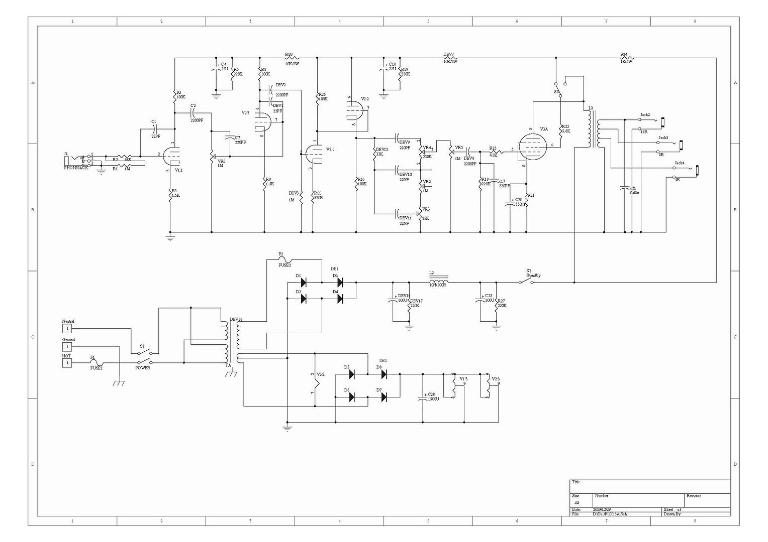
Original schematic (from thread referenced above):
picovalve.jpg


This modified drawing by duhvoodooman (at: http://www.mylespaul.com/forums/5471842-post221.html - want to give credit were due!):


shows how JC added the bright switch.

Putting the 1meg from V2:2 (grid to ground) will result in a 666k'ish grid leak. It looks like the original plan had a 1meg there. Not that it would be that big of a difference.

I'm wonder if JC accidentally put the switch and resistor on the wrong side. It looks like it would work correctly if R14/C13/switch were on the leg just to the left, after C3, the coupling capacitor.

Also wondering how usable that switch really is? Maybe just bypassing R14 with a jumper would be better (or as good) as adding a 1M resistor from V2:2 to ground.
 
I definitely plan on putting cathode bypass caps on as well. Not sure if switchable is worth the trouble.
 
I definitely plan on putting cathode bypass caps on as well. Not sure if switchable is worth the trouble.
It doesn't seem like too much trouble. The amp is pretty darn close to where I want it right now, so I'd like to keep the current circuit configuration as an option. I was even going further, wondering if I could somehow add a common-anode two-color LED as an indicator since each side of the switch has a connection to ground.

Sent from my DROID RAZR HD using Tapatalk 4
Not a lot of voltage on the cathode, so I'm not sure how well it would light. Worth trying though.

Reading duhvoodooman's thread, I would not have brought the cathode resistor up that high. I will probably try a 20uf and a 1uf, or .47uf bypass cap... If I make it switchable. Also, having some resistors (47k?) on the open/ground side of the caps will alleviate any popping from the switch. It looks like cathode bypass caps could be experimented with on all of the gain stages. Also, maybe put a 470pf/470k after the coupling cap from v1.
Oh, the common anode of the LED wouldn't be connected to the cathode of the tube. I'd probably wire that to the heater, which is DC here, isn't it? The cathodes of the LED would each be connected on the poles of the switch that connect to ground when the switch is flipped.

Yeah, I want to keep the stock cathode resistor value as I'm not looking to change the gain level.

Sent from my DROID RAZR HD using Tapatalk 4
Ah, yep, the heaters are dc. Hadn't thought of that.
 
So...

Amperex 12AX7 (long plate) in V1 + JJ ECC83S (short plate) in V2 + JJ 6CA7 + EVERYTHING dimed = HOLY FUCKING EVH!
 
The wife and kid are at the supermarket, so I figured I'd shoot a quickie with my phone. Therefore, the EQ doesn't quite sound right, my playing is sloppy as shit, and there's some weird skip towards the beginning of me playing that didn't actually happen.

However, I didn't make the mistake that every other Youtuber does... I didn't stand right over the mic while I'm playing so you don't have to hear me slapping the strings with my pick. :)


At some point I'm going to repeat the process, try not to play like ass, and put a proper mic in front of the amp. :)
 
I definitely plan on putting cathode bypass caps on as well. Not sure if switchable is worth the trouble.

Mine will stay stock except tubes. Haven't played mine yet as I have been busy with work, gigs and practice - I will get to it yet.

So...

Amperex 12AX7 (long plate) in V1 + JJ ECC83S (short plate) in V2 + JJ 6CA7 + EVERYTHING dimed = HOLY FUCKING EVH!

Nice combo!

I am partial to using Tung Sol so I may try a 5881 as well as 6CA7 (EL34) in the output section - eventually I will get there.

Dang, sounds huge. :thu:

Agreed...I hate to think of what my experiments will be.
 
Even the 2M grid leak? I'm gonna record some stock clips, then start w/that and then go nuts on it, lol.

Never been one to mod much unless it is absolutely necessary such as tubes. I just love amps for the way the original design was intended rather than redirecting or trying to make it sound like something else - that is just me.
 
After rereading your note, I will explore to see if it will be necessary.
It seems like a lot of people are starting w/that. I'll try it and see if the bright switch is useful/effective - if not, I'll probably just remove it and re-purpose the hole the switch was in.

Anyway, looking forward to getting the amp.
 
Back
Top