telecaster911
Kick Henry Jackassowski
I decided to mod my old DS-1 that I don't use. Basically, I don't use it because it's a little harsh and lacked definition. First, I made a trip out to the garage to get the parts necessary for the build.
Bill of material
2 ea 1uf capacitors
1 ea 1uf electrolytic capacitor
1 ea .033uf capacitor
1 ea diode 1N4001
1 ea resistor 2.2K 1/4 watt is fine
1 ea resistor 15K 1/4 watt
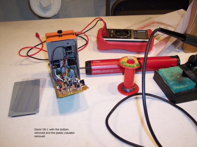
Now that I have my parts and all the tools together to r&r the parts, I open up the DS-1. Remove the 4 screws and remove the bottom along with insulating plastic. Set this aside. Pull the board out starting at the stomp side or bottom of the pedal, swinging the board out of the ac adapter cutout in the case. The wires are short and you don't want to work them back and forth too many times.
It should look like this.
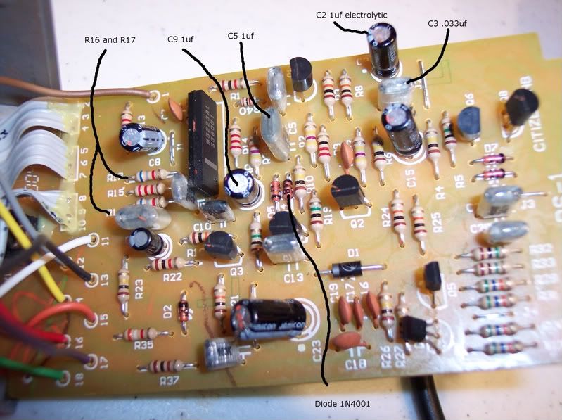
Next, you will want to identify the components that you are replacing.
C2, change to 1uf electrolytic
C3, change to .033uf
C5, change to 1uf
C9, change to 1uf
D4, change to 1N4001
R16, change to 2.2K resistor
R17, change to 15K resistor
Here are the locations with the new values listed.
Now, you will want to remove the old components. The capacitors are pretty easy to remove, especially if you have dry wick. I found that the best way to remove the resistors and the diode was to snip the component out leaving just the leads still soldered in. Then dry wick and remove the leads from the track side of the board.
Here are the locations of the components on the track side.
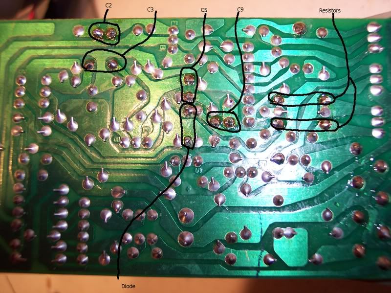
Now that you have your components removed, make sure the holes are open using the dry wick. The diode D4 needs to have the holes opened to fit the legs of the larger diode. I had a .038 inch bit handy so I just spun it in my fingers and opened the hole. Do this from the component side so that you don't lift the track from the board.
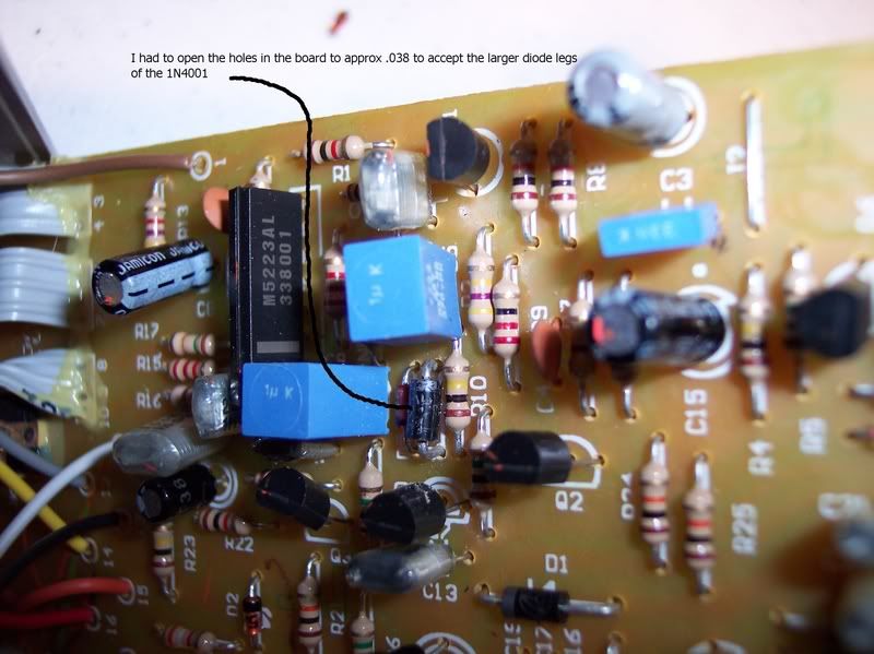
It's time to start stuffing the board with the new components. I would start with the resistors, then the diode, and then the caps. I didn't do it in this order and it was tough to get the diode in with the caps in the way. Plus, the only diode I could find had the leads trimmed short already. Make sure you observe the polarity on the electolytic cap C2. Negative goes toward the dot. Also, make sure you observe the polarity on the diode. The silver stripe is oriented toward the C5 cap or to the right.
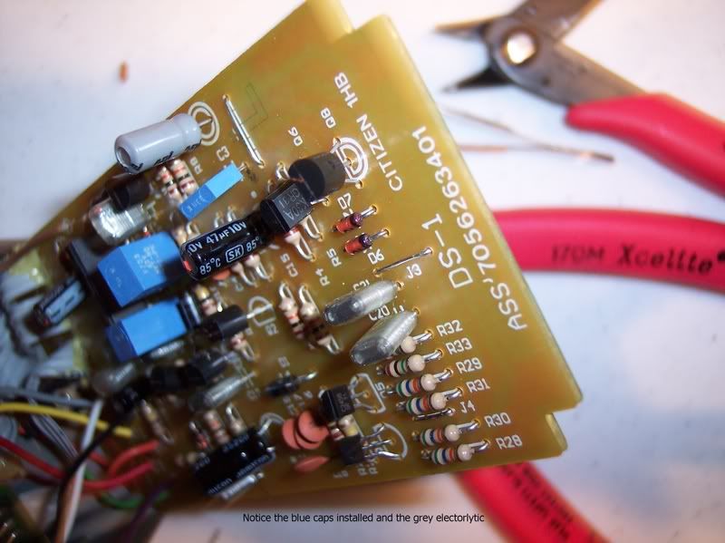
Here is what the new components look like on the board. The 3 blue blocks are the new caps and the grey can is the new electrolytic in the C2 location.
Now, I would try the pedal at this point before you button it up.
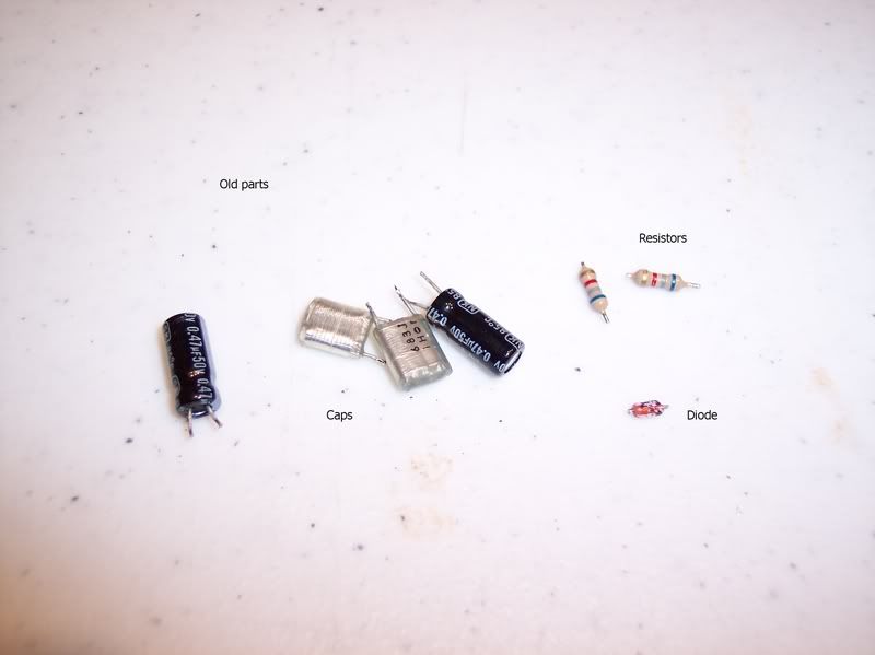
Here is the parts that should have been removed.
Now that everything is working, we can put the board back in, making sure to put the ac adapter socket into the case first. Do not force anything. The board should just swing back in. Watch that the board doesn't catch on the ledge at the bottom of the pedal case, it needs to go into the pedal farther than this. Make sure you put the plastic insulator back in between the board and the bottom.
That's it. Now you have an awesome Marshall in a box. AOK It really made a huge difference in this pedal. smi The tone knob is now usable beyond 9 o'clock AOK
Clip, sorry I promised no more bandmaster clips. First part is amp only. The different gain levels are just rolling the volume knob up and down and switching pickups. I probably needed to turn up the tone knob a little on the pedal. The distortion was at 3 o'clock. Guitar is stock strat.
http://hc.bloodyvelvet.com/files/129/bandmaster%20with%20modded%20DS-1.mp3
credits and thanks to these guys ---> http://www.erikhansen.net/?page_id=28 http://www.premierguitar.com/Magazine/Issue/2008/Feb/Boss_DS_1_Mods.aspx
Bill of material
2 ea 1uf capacitors
1 ea 1uf electrolytic capacitor
1 ea .033uf capacitor
1 ea diode 1N4001
1 ea resistor 2.2K 1/4 watt is fine
1 ea resistor 15K 1/4 watt
Now that I have my parts and all the tools together to r&r the parts, I open up the DS-1. Remove the 4 screws and remove the bottom along with insulating plastic. Set this aside. Pull the board out starting at the stomp side or bottom of the pedal, swinging the board out of the ac adapter cutout in the case. The wires are short and you don't want to work them back and forth too many times.
It should look like this.

Next, you will want to identify the components that you are replacing.
C2, change to 1uf electrolytic
C3, change to .033uf
C5, change to 1uf
C9, change to 1uf
D4, change to 1N4001
R16, change to 2.2K resistor
R17, change to 15K resistor
Here are the locations with the new values listed.

Now, you will want to remove the old components. The capacitors are pretty easy to remove, especially if you have dry wick. I found that the best way to remove the resistors and the diode was to snip the component out leaving just the leads still soldered in. Then dry wick and remove the leads from the track side of the board.
Here are the locations of the components on the track side.

Now that you have your components removed, make sure the holes are open using the dry wick. The diode D4 needs to have the holes opened to fit the legs of the larger diode. I had a .038 inch bit handy so I just spun it in my fingers and opened the hole. Do this from the component side so that you don't lift the track from the board.
It's time to start stuffing the board with the new components. I would start with the resistors, then the diode, and then the caps. I didn't do it in this order and it was tough to get the diode in with the caps in the way. Plus, the only diode I could find had the leads trimmed short already. Make sure you observe the polarity on the electolytic cap C2. Negative goes toward the dot. Also, make sure you observe the polarity on the diode. The silver stripe is oriented toward the C5 cap or to the right.
Here is what the new components look like on the board. The 3 blue blocks are the new caps and the grey can is the new electrolytic in the C2 location.


Now, I would try the pedal at this point before you button it up.
Here is the parts that should have been removed.

Now that everything is working, we can put the board back in, making sure to put the ac adapter socket into the case first. Do not force anything. The board should just swing back in. Watch that the board doesn't catch on the ledge at the bottom of the pedal case, it needs to go into the pedal farther than this. Make sure you put the plastic insulator back in between the board and the bottom.
That's it. Now you have an awesome Marshall in a box. AOK It really made a huge difference in this pedal. smi The tone knob is now usable beyond 9 o'clock AOK
Clip, sorry I promised no more bandmaster clips.
 First part is amp only. The different gain levels are just rolling the volume knob up and down and switching pickups. I probably needed to turn up the tone knob a little on the pedal. The distortion was at 3 o'clock. Guitar is stock strat.
http://hc.bloodyvelvet.com/files/129/bandmaster%20with%20modded%20DS-1.mp3
credits and thanks to these guys ---> http://www.erikhansen.net/?page_id=28 http://www.premierguitar.com/Magazine/Issue/2008/Feb/Boss_DS_1_Mods.aspx
