Modern Saint
Starve your Fear, Feed your Dream!
Here's a picture of the $200 EJ fuzz face. Looks even simpler then the BYOC, lol.
View attachment 3339
Almost exact with one pot and a resistor more in the BYOC, that's all.
Here's a picture of the $200 EJ fuzz face. Looks even simpler then the BYOC, lol.
View attachment 3339
Two germanium transistors? Never saw the schematic. Irony is on an early LPB-1 (circa 77) it had just two silicon transistor's with the gain curve was linear. Fuzz face must be running assymetrical or blasting the hell out of the Germanium into saturation.
Almost exact with one pot and a resistor more in the BYOC, that's all.
yep, two transistors. the Tonebender is three, the Big Muff is four.
the thing in the middle isn't a pot, it's a for a screw so you can keep the bottom of the pedal secure.

True. I mean, I've watched them open the Bonamassa fuzz and Eric Johnson fuzz, and neither of them had anything vastly different then that picture I posted. Obviously they're different, I just never realized how simple the build was. Those sexy finishes must cost Dunlop a fortune.Or at least that's what they want you to think, lol.

True. I mean, I've watched them open the Bonamassa fuzz and Eric Johnson fuzz, and neither of them had anything vastly different then that picture I posted. Obviously they're different, I just never realized how simple the build was. Those sexy finishes must cost Dunlop a fortune.
My 70's Bigmuff had more. IIRC 6 Transistors and an LM741 single op amp.
View attachment 3338
You are looking at the wrong pic
aha.
my Foxrox Hot Silicon Fuzz was the same circuit. he made the bias a fuzz sized pot instead of a trimpot. all it does is starve the battery anyway. cool feature.
That's clever. I might have to look into those. Or are their clones of that one, too?
aha.
my Foxrox Hot Silicon Fuzz was the same circuit. he made the bias a fuzz sized pot instead of a trimpot. all it does is starve the battery anyway. cool feature.
Just as I thought. Assymetrical causing the transistor curve to go non-linear and into either saturation or cutoff.
layman's terms please, or a longer technical explanation.


Tone is the finish and the graphics!
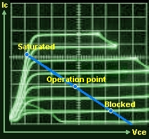
Typical gain curves of either an NPN or PNP transistor.
The operating point is when your signal is linear the wave form is even on both sides.
As the signal is pushed towards saturation or cutoff (blocked in the transistor curve), one side of the signal begins to go into distortion.

Rofl, screw layman's terms!
Rofl, oh I know. I just found it comical that he didn't try layman's terms first and just went all out with graphs and everything.that was the longer technical explanation.
Rofl, oh I know. I just found it comical that he didn't try layman's terms first and just went all out with graphs and everything.